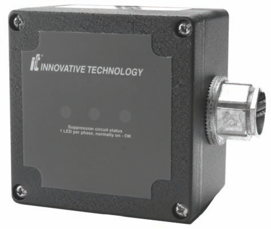
XT-40 Models

Product Name:XT-40 Models
Product Model:XT40 3Y201,XT40 1P201
Updated:2010.04.13
Views:3

X T 4 0 R A N G E
XT40 models provide cost effective surge suppression for your electrical and electronic equipment. UL1449 listed circuitry intercepts potentially damaging transients at small service entrance or sub-distribution panel locations before they can affect valuable equipment. Compact size provides application flexibility and close proximity mounting to minimise parallel connection lead lengths for optimum product performance.
GENERAL SPECIFICATIONS:| DESCRIPTION: | Parallel configured, hard wire connected Transient Voltage Surge Suppressor providing 40kA per phase peak surge current. |
| APPLICATION: | Location categories B and A, medium and low exposure level, AC power distribution boards,final circuit distribution boards and individual equipment isolators. |
| WARRANTY: | 10-Year Free Replacement warranty. |
| UNIT LISTINGS: | UL1449 Second Edition. |
| QUALITY: | ISO 9001: 1994 Quality System Certification BSI FM 30833. |
MECHANICAL SPECIFICATIONS:
| ENCLOSURE: | IP66 rated aluminium weatherproof enclosure. |
| MOUNTING: | Factory installed internally threaded conduit fitting and multi-point mounting holes. Flush mounting plate available, order list number ZPLATE-2. |
| CONNECTION: | Standard products include approx. 450mm factory fitted stranded cable #10 AWG (≈ 6mm2). |
| SHIPPING WEIGHT: | 1.3kg. |
ELECTRICAL AND PERFORMANCE SPECIFICATIONS:
| CIRCUIT DESIGN: | Bi-directional, parallel configured, Threshold Response circuitry utilising advanced component encapsulation technology. |
| PROTECTION MODES: | All Mode: line to neutral & line to line (normal mode) and line to earth & neutral to earth (common mode). |
| SUPPLY FREQUENCY: | 50-420Hz. |
| RESPONSE TIME: | ≤ 1 nanosecond. |
| EMI/RFI ATTENUATION: | Up to 41dB normal mode, up to 40dB common mode. |
| CAPACITANCE: | 2.3μF. |
| CIRCUIT DIAGNOSTICS: | 1 LED indicator per phase, normally on. |
TEST PERFORMANCE DATA:
| LIST NUMBER | SYSTEM CONFIGURATION |
NOMINAL SYSTEM VOLTAGE(rms) |
ANSI/IEEE C62.41 - 1991 MEASURED LIMITING VOLTAGE TESTS* | ||
| A3 RING WAVE 2,000V 200A 90° PHASE ANGLE |
B3/C1 IMPULSE WAVE, 6,000V 3,000A 90° PHASE ANGLE |
C3 IMPULSE WAVE, 20,000V 10,000A 90° PHASE ANGLE | |||
| XT40 1P201 | SP N & E | 200, 208, 220 230, 240 |
L-N <500V | L-N <600V | L-N <1500V |
| XT40 3Y201 | TP N & E STAR CONNECTED |
220/380 230/400 240/415 277/480 |
L-N <500V | L-N <600V | L-N <1500V |
